|
|
Conversion of a Gossen Luna Pro CdS
(Lunasix 3) Light Meter to silver oxide cells
by Sarah Fox
I love my little Gossen Luna Pro, which I purchased back in the mid 1970's. (In some parts of the world it is known as the Lunasix 3 meter.) To use a term coined in the movie, "Mr. Mom," it's become my "woobie." I love the smell of its leather case, its silky smooth action, its stability, and its amazing sensitivity. That's why it was so upsetting when I could no longer get the IEC MR9 1.35V mercury cells that were needed to power it. I tried the replacement 625 silver oxide 1.55V cells that were the correct size replacement. Yes, the meter powered on. The battery check was quite high, predictably, and not surprisingly, the meter read high as well -- by about 2 stops. Horrors!
A bit of searching on the Internet turned up some adapter I could buy for $40 or so, that would let me use the silver oxide batteries. Two adapters would be required! Short of that, I could use a zinc air battery at 1.4V or a Wein cell at 1.35V, but at a high cost and with very little battery life. I figured I would try to adjust my meter to use the silver oxide cells, rather than to give in to the high cost and/or low battery life of the alternatives. I figured if I were to fail, I could apply all the money I saved towards a new Gossen. The worst that could happen would be that I would fail. In fact I succeeded, and so I'm passing along this info to other Luna Pro owners. Others have followed my instructions successfully too. Of course use these tips at your own risk. I'm not responsible for any damage or loss of accuracy to your meter, nor am I responsible for any pictures ruined due to incorrect exposure! If you can provide any further information, I'll post it here. (Please email me about it.)
One note before I begin: When I did my repairs and recalibration, I selfishly didn't take photos for others to see. I requested photos from others on this page, and Mr. Lukas Friedl kindly provided a few. Also Mr. S. Velt was so kind as to refresh my memory as to which adjustment was which (as my original instructions simply instructed people to use trial and error -- because I couldn't remember which was which). Anyway, thanks to these two gentlemen for helping to make this a more informative and accurate page. The Internet is truly a wonderful place when people come together to share their knowledge! Now on to the instructions:
 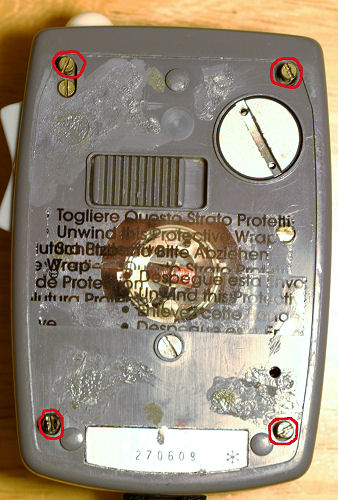
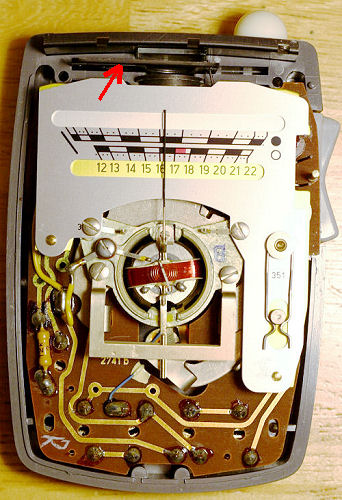  First I opened up the meter. This was done by removing the aluminum plate on the back of the meter. Carefully pry up the edge with a small knife, careful not to bend it. It is attached with adhesive. (Michael Doran kindly wrote to tell me that pre-heating the plate with a hair dryer for about 30 sec causes it to slide off when a blade is inserted underneath! His choice of insertion point was around the serial number.) Once the plate is removed, there are four long screws that can be removed (red circles in photo to upper right) to lift off the top half of the shell. There is a meter centering part on the back side (red circle in photo to upper left). Either remove it or hold it in place with a piece of scotch tape. Otherwise it could fall out and get lost. Once the shell is open, be careful not to let the half-silvered filter (red arrow on image to the right) flip out of the meter when the low-range button is pressed! First I opened up the meter. This was done by removing the aluminum plate on the back of the meter. Carefully pry up the edge with a small knife, careful not to bend it. It is attached with adhesive. (Michael Doran kindly wrote to tell me that pre-heating the plate with a hair dryer for about 30 sec causes it to slide off when a blade is inserted underneath! His choice of insertion point was around the serial number.) Once the plate is removed, there are four long screws that can be removed (red circles in photo to upper right) to lift off the top half of the shell. There is a meter centering part on the back side (red circle in photo to upper left). Either remove it or hold it in place with a piece of scotch tape. Otherwise it could fall out and get lost. Once the shell is open, be careful not to let the half-silvered filter (red arrow on image to the right) flip out of the meter when the low-range button is pressed!
My original intent was to install a 2.7V zener diode and resistor to stabilize the voltage at the correct level. Unfortunately the circuit is laid out in such a way that this cannot be done without extensive circuit modification. I abandoned that thought. On further examination of the circuit, I realized that it has no active components and can be adjusted to the new (higher) battery voltage via the variable resistors on the circuit board.
Note: Although I think recalibrating the meter is probably the best approach, another approach was suggested to me by Walter DeGroot. He said he's successfully rewired devices for the higher voltage cells simply by inserting a couple of Schottky diodes in series with the batteries. These diodes have a small forward bias voltage that must be overcome before current can flow. By stacking the right number and type of Shottky diodes in series with the cells, the total effective voltage can be lowered to the correct 2.7V (2 x 1.35V). What I don't know is whether the forward bias voltage is stable with current. In my experience, bias voltage on semiconductor devices rises for very small currents, but I don't know whether this would be an issue within the operating range of the LunaPro. (I haven't tried it.) If you decide to recalibrate, instructions follow.
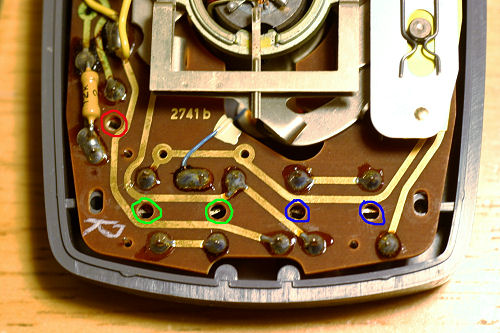
The first adjustment is the the easiest -- the meter zero point. Remove the batteries, and press any switch to release the needle. It should fall to the line at the left of the scale. If not, adjust it with the zero-adjust on the back (red circle on photo at top left). Next, replace the batteries, and refer to the photograph to the lower right to make the 5 scale adjustments. The first adjustment is for the battery level indicator, indicated with the red circle. The variable resistor for this adjustment is located on the other side of the board. It should be adjusted with a small precision screwdriver inserted through the hole. With fresh batteries, adjust the battery level adjustment so that the meter reads at the top end of the battery check red zone on the face of the meter (between EV 17 and EV 17 2/3 in the photo to the above left).
 Next, the meter sensitivity must be calibrated. Before performing any adjustments, mark the positions of the variable resistors with a sharpie on the PC board. You may need to refer to these later. However, once a variable resistor is turned, the alignment mark is insufficient to accurately restore the original setting! Also, before you attempt any adjustments, you will of course need an accurate meter to calibrate against. Finally, you need a target area. I would suggest a wall, illuminated by a light with a dimmer. Next, the meter sensitivity must be calibrated. Before performing any adjustments, mark the positions of the variable resistors with a sharpie on the PC board. You may need to refer to these later. However, once a variable resistor is turned, the alignment mark is insufficient to accurately restore the original setting! Also, before you attempt any adjustments, you will of course need an accurate meter to calibrate against. Finally, you need a target area. I would suggest a wall, illuminated by a light with a dimmer.
There are two pairs of variable resistors -- one on the right (blue circles), and one on the left (green circles). The leftmost pair are the lower light range adjustments, and the rightmost pair are the higher light range adjustments. The two sides are symmetrical with each other, such that the inside adjustments adjust the lower ends of their respective scales, and the outer adjustments control the upper ends of their scales.
The basic adjustment procedure is easy: Select a position at the high end of the range you are going to adjust -- probably either 11 or 21 on the scale. Adjust the light shining on the wall to the desired brightness using the reference meter. Now adjust the LunaPro's outermost variable resistor for that range to make the LunaPro reading agree with the reference meter's reading. Now repeat this procedure with a light level at the lower (but not lowest) end of the scale, probably a 4 or 13, and adjust the innermost variable resistor to achieve the correct reading. These adjustments are interactive, so it will take some back-and-forth adjusting before the settings are eventually correct. Now check the meter at various EVs throughout the range. The Luna Pro should read the same as the reference meter througout. Now repeat the procedure with the other light range, using the other pair of variable resistors. Be aware that the Luna Pro will accurately read light levels much lower than most cameras will accurately meter. At ultra-low light levels, the best test of metering accuracy is a test exposure with a digital camera. A correct exposure of a uniformly illuminated wall will yield a histogram with a narrow peak right in the middle. Make sure you're looking at the luminance histogram (as metering is based on luminance), rather than the RGB histogram. If RGB is your only option, just make sure you're correctly white balanced to your target.
That's it! With about a half hour of tweaking, your trusty little Luna Pro should be back in service, as accurate as it ever was. Of course a word of caution is in order: Mercury cells were originally used because of their voltage stability. You won't have the same stability with the modern 1.5V cells. Thus, you should watch your battery level carefully. When it strays outside of the red zone, replace the cells.
One more note: I had to perform one repair on my meter as well, after a long duration in storage. The lens housing over the CdS cell had collected condensation and had to be cleaned inside. Executing this repair was rather delicate, but not impossible. The first step is to open the meter, as above. Then with the meter at the left-most position, remove the two screws holding the face plate. CAREFULLY pull out the needle stop tabs from underneath, and set them aside, making sure to note their position and making sure not to confuse the two of them. Now, VERY CAREFULLY slide the face plate out, under the needle, making certain not to flex/bend the needle. Slowly depress the low-light switch, so that the half-silvered filter slides to the right and tilts out. Lock the meter needle in the right-most position. Slide the CdS cell and lens housing upwards, out of its mounting slot, and free up the wire that connects it. The CdS cell is held into the housing with three tabs on the backside. Carefully file these away with a Dremel tool or an engraver. Gently pry the CdS cell out of the backside of the lens housing. Clean the lens and housing with alcohol and Q-tips. Press the CdS cell back into the housing and (optionally) re-affix it with superglue. (Personally, I didn't see the need to glue it, as it fit pretty tightly anyway.) After cleaning the glass and half-silver filter, reassemble in reverse order. If the needle centering part falls out of its socket, replace it so that the pin fits into the slot in the meter movement. The back plate can just be stuck back in place with the adhesive that's on it.
Please note that you can download a manual for this classic light meter from Peter Marquis-Kyle here.
Links:
Home
Galleries
About Us
Photoediting Services
On-Location Services
Portraiture
Architectural Photography
Commercial Photography
Special Events
Web Design
Articles
Projects
FAQ
Contact
Site Map
Notice: All images and web content are copyrighted by Sarah Fox, Earline Thomas, and/or Graphic Fusion, will all rights reserved.
Printing or distribution of this material is prohibited.
|