|
|
Vivitar 285HV Modifications
Sarah Fox
The Vivitar 285HV, just like the Vivitar 283, is a classic flash. It's powerful, basic, robust, accurate, and cheap. It was originally designed for and used primarily for on-shoe work. However, its real place is for highly portable off-shoe work, and thus it is loved by professional photographers everywhere. Although the 285 is an excellent workhorse, it can be even better with a couple of modifications.
External Lead-Acid Battery
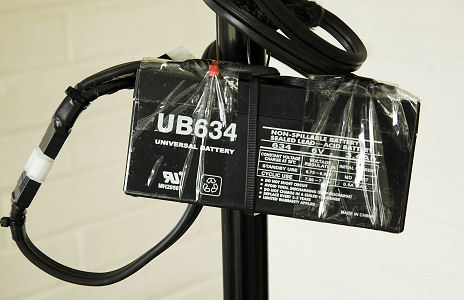  The first of these modifications is beefier power supply. Although the 285HV can be fed with a high voltage power supply, hence the "HV" designation, it also has a strong enough charging circuit that one can dump a very large current through the battery connections, resulting in a very rapid cycle time (less than 2 sec on my modified flashes after a full discharge). When designing my system, I could have bought the more expensive gel cell lead-acid batteries, but I opted instead for the sealed, flooded, lead-acid variety. These batteries are just plain cheap. I paid about $15 each for the Universal Battery 634, rated at 6VDC, 3.4 Ah, shown here hanging from a light stand. Each battery has two Molex connectors wired to it, to allow for simultaneous connection to a flash and charging from a UB automatic 1000 mA wall charger (not shown). The first of these modifications is beefier power supply. Although the 285HV can be fed with a high voltage power supply, hence the "HV" designation, it also has a strong enough charging circuit that one can dump a very large current through the battery connections, resulting in a very rapid cycle time (less than 2 sec on my modified flashes after a full discharge). When designing my system, I could have bought the more expensive gel cell lead-acid batteries, but I opted instead for the sealed, flooded, lead-acid variety. These batteries are just plain cheap. I paid about $15 each for the Universal Battery 634, rated at 6VDC, 3.4 Ah, shown here hanging from a light stand. Each battery has two Molex connectors wired to it, to allow for simultaneous connection to a flash and charging from a UB automatic 1000 mA wall charger (not shown).
 The secret to connecting this ample battery to the flash is to wire the cord into a fake battery. The approach most often taken is to use Buss RFN-R-30 30A fuses, which are the exact same size as AA batteries. Two of these fuses are shown soldered to a spiral cord on the left. If so desired, these fuses could be inserted into the Vivitar battery carrier and inserted into the battery compartment, with the cord exiting through a notch filed into the battery door. However, the fuses shown here are actually for use in my Canon 550EX flash, for on-shoe work. (I carry the battery in my pocket.) The preferred approach for connecting to a Vivitar 285, for those who have basic woodworking skills, is to fashion an insert that is the same size and shape as the battery compartment. The insert is shown in the top middle of this picture. The secret to connecting this ample battery to the flash is to wire the cord into a fake battery. The approach most often taken is to use Buss RFN-R-30 30A fuses, which are the exact same size as AA batteries. Two of these fuses are shown soldered to a spiral cord on the left. If so desired, these fuses could be inserted into the Vivitar battery carrier and inserted into the battery compartment, with the cord exiting through a notch filed into the battery door. However, the fuses shown here are actually for use in my Canon 550EX flash, for on-shoe work. (I carry the battery in my pocket.) The preferred approach for connecting to a Vivitar 285, for those who have basic woodworking skills, is to fashion an insert that is the same size and shape as the battery compartment. The insert is shown in the top middle of this picture.
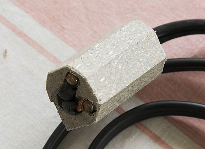 Here is a close-up of the insert. It is constructed from plastic lumber, specifically a picket for construction of a banister or stair rail. The plastic is made from recycled plastic bags and is very easy to machine. I made a long stock piece by shaping it with a hand planer. The shape ensures that it can only be inserted one way into the battery compartment. After shaping the stock and cutting off pieces to the correct length, I drilled a hole for a rather meaty zip cord and soldered those ends to a couple of brass screws. The threads were pressed into the plastic, just leaving the heads exposed. The other end of the zip cord was soldered to a Molex connector. Here is a close-up of the insert. It is constructed from plastic lumber, specifically a picket for construction of a banister or stair rail. The plastic is made from recycled plastic bags and is very easy to machine. I made a long stock piece by shaping it with a hand planer. The shape ensures that it can only be inserted one way into the battery compartment. After shaping the stock and cutting off pieces to the correct length, I drilled a hole for a rather meaty zip cord and soldered those ends to a couple of brass screws. The threads were pressed into the plastic, just leaving the heads exposed. The other end of the zip cord was soldered to a Molex connector.
I've seen this same general technique described elsewhere, and I've not yeat heard of an overstressed/overworked/destroyed flash. However, I will caution that my Canon 550EX has developed a rattly sort of whine since I have used this method of powering it. Otherwise it functions fine. I would not use this method casually with an expensive flash, unless recycle time is of great importance (as it is with most professional photographers). If you use this method for your main flash, I would recommend you have another flash for backup.
Continuously Variable Power and 1/4" Sync Jack
Three aspects of the 285 make it somewhat annoying for me to use. The first is the use of PC sync cords to trigger the flash. PC cords are very fussy things, and they tend not to work very well or for very long. A more reliable, and much more servivceable, connection is the 1/4" plug that is used for studio flashes. The second annoying feature is the limited number of manual settings available -- full, 1/2, 1/4, and 1/16 power. Note there is no 1/8 power setting, nor is it possible to adjust power in increments finer than one stop. Finally, the power dial is difficult to read and set, particularly when the flash is mounted atop a stand in a darkened room.
 All three of these shortcomings can be remedied by making a simple replacement for the round sensor module on the face of the 285, which unplugs from the flash unit. The underlying connector contains contacts both for triggering the flash and for controlling its output power. I have seen various descriptions of this round connector on the web, but the pin diagrams I've seen are wrong, not corresponding to the pin numbers molded into the connector. When looking at the face of the flash, the #1 pin is in the 6:00 position, just adjacent to the alignment ridge. The pins are then numbered 1 through 5, proceeding in a clockwise direction. The resistance between pins 1 and 2 (GND) controls the output power. Shorting between pins 4 and 2 (GND) triggers the flash. Pin 5 runs from the center contact of the hot shoe connection. Shorting between pins 4 and 5 enables the hot-shoe trigger. All three of these shortcomings can be remedied by making a simple replacement for the round sensor module on the face of the 285, which unplugs from the flash unit. The underlying connector contains contacts both for triggering the flash and for controlling its output power. I have seen various descriptions of this round connector on the web, but the pin diagrams I've seen are wrong, not corresponding to the pin numbers molded into the connector. When looking at the face of the flash, the #1 pin is in the 6:00 position, just adjacent to the alignment ridge. The pins are then numbered 1 through 5, proceeding in a clockwise direction. The resistance between pins 1 and 2 (GND) controls the output power. Shorting between pins 4 and 2 (GND) triggers the flash. Pin 5 runs from the center contact of the hot shoe connection. Shorting between pins 4 and 5 enables the hot-shoe trigger.
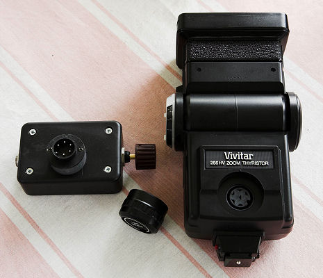
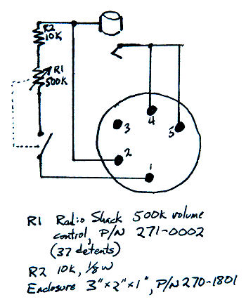 To make a sensor module replacement, I first disassembled the original sensor module, by removing the two screws on its back. I saved the plug piece and discarded the remainder of the module. Next, I attached wires to pins 1, 2, and 4/5 (shorted together). Then I screwed the connector to a 3/8" long section of PVC pipe and screwed the lid of a 2" x 3" x 1" black plastic project box to the other side of the pipe, with the wires extending through a hole in the lid. I mounted a 1/4" phone jack one one end of the box and a 500k potentiometer with 37 detents in the other end. I then wired the box per this shematic diagram. To make a sensor module replacement, I first disassembled the original sensor module, by removing the two screws on its back. I saved the plug piece and discarded the remainder of the module. Next, I attached wires to pins 1, 2, and 4/5 (shorted together). Then I screwed the connector to a 3/8" long section of PVC pipe and screwed the lid of a 2" x 3" x 1" black plastic project box to the other side of the pipe, with the wires extending through a hole in the lid. I mounted a 1/4" phone jack one one end of the box and a 500k potentiometer with 37 detents in the other end. I then wired the box per this shematic diagram.
The design allows for power settings between full power and roughly 1/32 power. A switch integrated into the potentiometer assembly opens the connection between pins 1 and 2 to set full power. When the switch is closed, the flash is attenuated per the setting of the potentiometer. The highest power level with the attenuator switched in is approximately 1/2 stop below full. I selected the potentiometer because of the 37 detents, which make setting power levels a bit more intuitive and repeatable. However, it uses a linear resistance scale, so the falloff in stops occurs much more rapidly on the low-power end of the scale. There are also log-taper potentiometers which might achieve a more regular falloff in stops from one end of the scale to the other. (Use whatever works for you.)
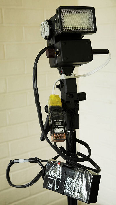 This is what the rig looks like when fully assembled. The flash is mounted to the top of an umbrella adapter, which is mounted atop the light stand. The 2"x3"x1" box I made is plugged into the front of the flash. On the left of the box is the knob that controls output power. This control has a pushbutton switch. In one position it produces full power. In the other position, the flash is attenuated per the rotation of the knob. The Wein UltraSlave is plugged into the box on the righthand side, via the 1/4" phone plug. I can also use the 1/4" jack to plug in a 16 channel radio slave I acquired through Ebay. The original PC sync cord jack and hot shoe are still intact, so I can also trigger the flash with a Sonia optical slave and hot shoe adapter pair, as well as with a Wein IR "peanut" slave. Hanging down below is the large lead-acid battery, which stores ample charge to last through an entire photo shoot, recycling in only 2 sec after a full discharge. This is what the rig looks like when fully assembled. The flash is mounted to the top of an umbrella adapter, which is mounted atop the light stand. The 2"x3"x1" box I made is plugged into the front of the flash. On the left of the box is the knob that controls output power. This control has a pushbutton switch. In one position it produces full power. In the other position, the flash is attenuated per the rotation of the knob. The Wein UltraSlave is plugged into the box on the righthand side, via the 1/4" phone plug. I can also use the 1/4" jack to plug in a 16 channel radio slave I acquired through Ebay. The original PC sync cord jack and hot shoe are still intact, so I can also trigger the flash with a Sonia optical slave and hot shoe adapter pair, as well as with a Wein IR "peanut" slave. Hanging down below is the large lead-acid battery, which stores ample charge to last through an entire photo shoot, recycling in only 2 sec after a full discharge.
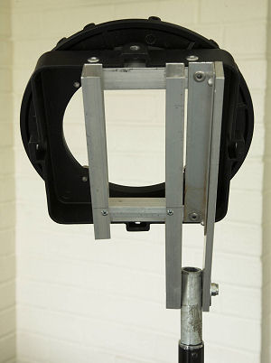
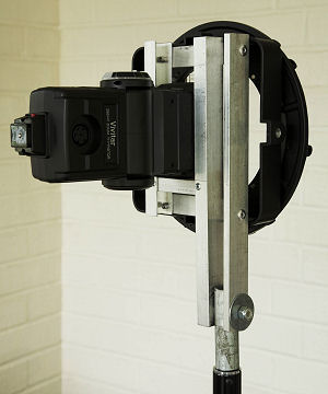
One final piece of equipment completes the picture. The 285 can be used very effectively in combination with a softbox. However, the mounts designed for conventional studio strobes are incompatible with the 285. If the weight of a softbox were suspended from the zoom head of the flash, the head would probably break off. For this reason it is necessary to customize the ring mount system. I did this with aluminum stock very commonly available at the local hardware store, as well as a piece of iron pipe. The iron pipe fits over the end of the light stand and is very firmly bolted between a piece of 1/4" x 1" aluminum (right) and 3/4" plywood edge molding (left). This joint is easy enough to flex, yet it is firm enough to hold the weight of even a large softbox. The flash slips into the channel formed by the 3/4" edge molding pieces. The remainder of the frame is constructed of 3/4" x 3/4" x 1/16" angle stock. Aside from the hinge bolt, all pieces are joined with rivets. This is the ring mount system without softbox attached:
In the end, I'm very happy with my modified gaggle of 285HVs. Their greatest strength is their portability, but with the right modifications they are also very robust and intuitive to use. Each flash, with full modifications, costs about $115 new and about $75 used. It's one of the few bargains available to pro photographers. I can fit four units, batteries, wall transformers, power control modules, hardware, and misc. junk neatly in a small case, and the outfit effortlessly rises to the challenge of almost any lighting situation.
Links:
Home
Galleries
About Us
Photoediting Services
On-Location Services
Portraiture
Architectural Photography
Commercial Photography
Special Events
Web Design
Articles
Projects
FAQ
Contact
Site Map
Notice: All images and web content are copyrighted by Sarah Fox, Earline Thomas, and/or Graphic Fusion, will all rights reserved.
Printing or distribution of this material is prohibited.
|